
- Key Takeaways
- What’s Included in a STEP File (And What Isn’t)
- Is .stp Different From .step?
- Is .stp Different From .step?
- Should You Export in Version AP203, AP214, or AP242?
- STEP vs IGES vs STL
- How to Export a STEP File from SolidWorks, Onshape, and Fusion
- Why STEP Files Get Rejected by Quoting Systems
- What Formats Does Komacut Accept?
- FAQ
A STEP file (.step or .stp) is a neutral 3D CAD file, defined by the international standard ISO 10303, that stores the exact solid geometry of a part or assembly as plain text. Because it isn’t tied to one vendor, it opens in SolidWorks, Onshape, Fusion, and the other main CAD and CAM programs, which is why manufacturers ask for it when quoting custom parts.
STEP stands for “Standard for the Exchange of Product model data.” The .stp and .step extensions are the same format.
For a manufacturer, it’s usually the most reliable way to receive your part design. However, your quote may be delayed if the file has not been exported properly.
That’s the problem we’ll cover in this article. We’ll go over what’s included in a STEP file, how it compares to STL and IGES, which version you should pick, and the mistakes to avoid when exporting your file.
Key Takeaways
A STEP file is a CAD file that encodes the geometry of a design in plain text.
Komacut’s instant quote accepts STEP files (.stp and .step), but only when they’re exported correctly.
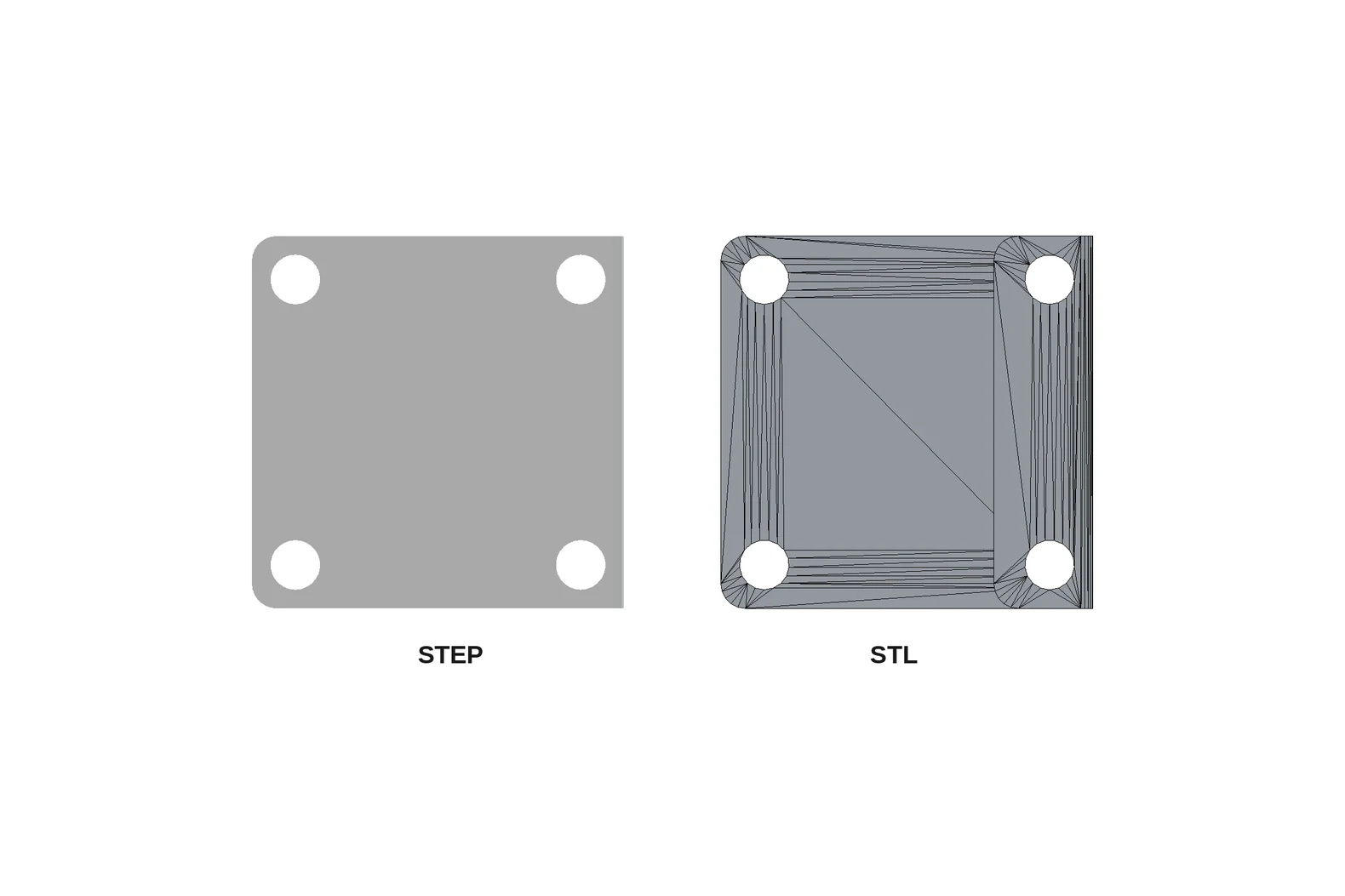
STL files are not a substitute for STEP files, because they approximate curved surfaces with flat triangles instead of storing the exact geometry, which makes them unsuitable for metal parts.
Common issues when exporting STEP files include a file with no closed solid or more than one, features the platform won’t quote automatically, and bent parts modeled without your CAD program’s sheet metal tools.
Table of Contents
- Key Takeaways
- What’s Included in a STEP File (And What Isn’t)
- Is .stp Different From .step?
- Should You Export in Version AP203, AP214, or AP242?
- STEP vs IGES vs STL
- How to Export a STEP File from SolidWorks, Onshape, and Fusion
- Why STEP Files Get Rejected by Quoting Systems
- What Formats Does Komacut Accept?
- Frequently Asked Questions
What’s Included in a STEP File (And What Isn’t)
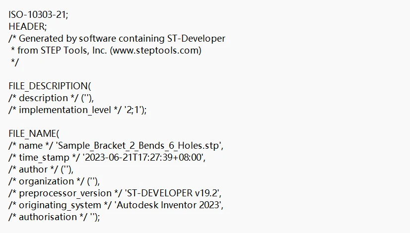
Open any STEP file in a text editor and the first line will read ISO-10303-21;. That’s because Part 21 of that standard (first issued in 1994, with the current 2016 edition having been reconfirmed in 2022) defines the plain-text encoding for STEP files.
Below that header will be a series of numbered entities (#10, #11, #12, and so on) that describe faces, curves, points, and how they join together to form a closed solid.
All in all, the file will include the exact geometry for the part (not an approximation), its assembly structure (if the file was exported as an assembly), unit of length, and colors (in some versions).
However, as Onshape’s documentation states, one thing that’s not included is the feature or parametric history. This means your supplier essentially receives a “dumb” solid. They can measure the part, unfold it, and cut it, but they can’t roll back your extrude or edit the sketch behind a flange. That’s generally a good thing when you’re submitting your part for a quote, because it gives the supplier all the information they need without allowing them to accidentally make changes to your design.
Is .stp Different From .step?
No, they’re the same format, contain the same exact information, and are compatible with all the same software. In fact, Annex L of ISO 10303-21 recommends both .stp and .step for files written to the standard’s application protocols.
If a supplier asks for “STEP” and your design was exported as an .stp file, don’t rename or convert the file. Send it as is. They’ll be able to open it.
Should You Export in Version AP203, AP214, or AP242?
We recommend exporting in AP214 unless you’re asked otherwise.
To explain why, let’s start with the basics. Most CAD programs will ask you to choose an application protocol (AP) when saving your STEP file. What the file can describe will be determined by the protocol you choose.
| Protocol | Origin | What it adds | When to use it |
|---|---|---|---|
| AP203 | Aerospace and defense (PDES, Inc.) | Geometry and assembly structure, no color | Only if a customer specifies it |
| AP214 | Automotive (ProSTEP iViP and SASIG) | Geometry plus body, face, and curve colors | Default to this unless asked for a different version |
| AP242 | Merger of AP203 and AP214 (first published 2014) | 3D tolerances and product manufacturing information (PMI) | When your supplier asks for annotated models |
Color is one of the major differences. As SolidWorks’ STEP page confirms, its translator can handle colors in the AP214 protocol, but not in AP203. The current AP242 is ISO 10303-242:2025, whose scope includes dimensional and geometrical tolerance data.
In most cases, exporting in AP214 will be your best option, because your file will have everything needed to provide you with a quote (your part’s exact geometry, its assembly structure, units, and color).
But why not AP242? After all, it covers everything AP203 and AP214 do but also adds tolerances and manufacturing annotations. Those features are useful for model-based definition workflows. But if you’re sending a 2D drawing with your tolerances on it, there is no benefit to exporting in AP242.
STEP vs IGES vs STL
All three file types are able to contain a 3D model, but they follow different standards and don’t include the same elements.
| File format | STEP (.stp, .step) | IGES (.igs, .iges) | STL (.stl) |
|---|---|---|---|
| Defined by | ISO 10303 (international standard) | ANSI Y14.26M-1981 (US standard) | 3D Systems, 1988 (de facto) |
| Geometry | Exact solids and surfaces | Exact surfaces and curves | Triangle mesh only |
| Curves and holes | Mathematically exact | Mathematically exact | Approximated by flat facets |
| Good for | Quoting and manufacturing metal parts | Legacy systems | 3D printing |
IGES is the predecessor to STEP. The National Institute of Standards and Technology (NIST) traces the origin of the IGES format back to 1980 when its first draft came out under the National Bureau of Standards before becoming an ANSI standard in 1981. Many programs can still read IGES files, but Komacut doesn’t accept them, and any neutral file can translate poorly. As Onshape warns, the data imported from the files may end up being “a series of surfaces or parts instead of a solid or cohesive body.” A quoting platform needs one closed solid to base a quote on, so it will reject a file that arrives that way.
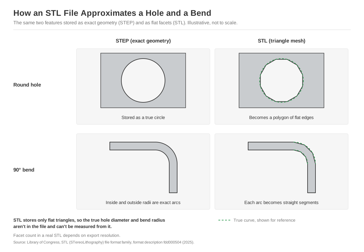
STL is the wrong format for metal parts. That’s because it describes a surface as triangles, and as the Library of Congress’s entry on STL points out, it can take thousands of triangles to approximate a smooth curve. Meanwhile a few spline or NURBS curves will describe it exactly. This means a laser-cut hole or a bend radius in an STL will be described as a polygon, so its true diameter or radius can’t be measured.
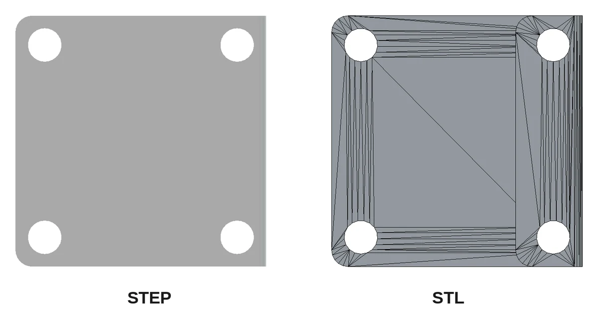
Use STL for 3D printing, but stick with STEP for everything else.
How to Export a STEP File from SolidWorks, Onshape, and Fusion
On any software, finding the export button in the menu is easy. The important part is making sure the settings are correct.
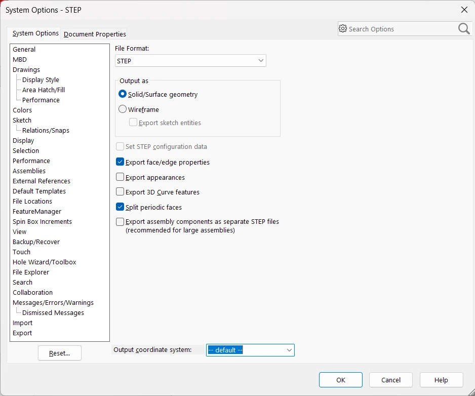
In SolidWorks, click on File, then Save As. Choose STEP AP214 as the file type, then click Options. Under “Output as,” keep Solid/Surface geometry (the wireframe option exports curves only). The Output coordinate system setting applies a transformation on export, so leave it at default unless the part needs to be placed somewhere specific. SolidWorks writes the document’s unit of length into AP203 and AP214 files.
In Onshape, right-click the part in the Parts list (not the whole Part Studio, if it holds several bodies) and choose Export, then STEP.
One thing to watch for is the unit length. If you don’t tick “Use custom units for export,” Onshape will write the STEP file in meters. The part will still be correct, but exporting in the unit you designed in (millimeters or inches) means the numbers on the file will match those on your drawing.
In Fusion, click on File, then Export, and set Type to STEP Files (.stp .step). Hide any bodies you don’t want in the file before exporting it.
If you’ll be uploading the file to get a quote for your part, make sure to export only one part per file. An assembly STEP will show how everything fits together, but it’s the wrong info to provide when you’re just trying to price a single component.
Why STEP Files Get Rejected by Quoting Systems
When you upload your STEP file to a quoting platform, it will automatically read the file, identify the part in the design (and unfold it if it’s made for sheet metal), and check to ensure that it falls within the manufacturer’s process limits. But in some cases, the file will be rejected.
When this happens on Komacut, you’ll get a message explaining why your STEP file couldn’t be accepted. The export-related messages fall into four groups.
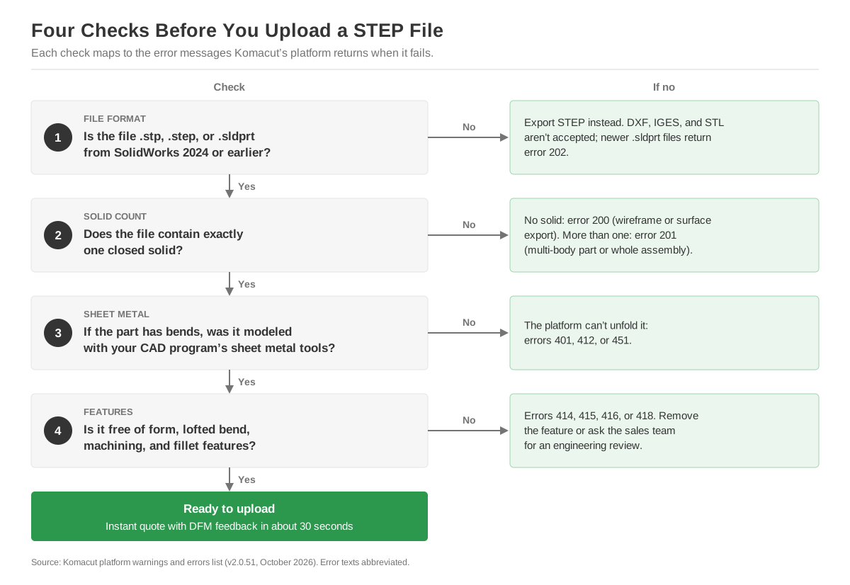
Your file contains more than one closed solid (or does not contain any). “No 3D Solid entities detected” (error 200) means the file has surfaces or curves but no closed solid. That’s what a wireframe or surface-only export produces. If you get “Multiple 3D Solid entities detected, please keep only one 3D Solid” (error 201), that means the file either contains a multi-body part or is a whole-assembly export. Both issues can typically be fixed by modifying the export settings, so you won’t need to change anything in the model itself.
Bent parts that haven’t been modeled as sheet metal. Our upload page specifies that sheet metal designs “must be made using 3D sheet metal modules.” In practice that means using your CAD program’s sheet metal tools, which ensures that the part will be built with real bend radii and uniform thickness. Otherwise, the platform won’t be able to convert your part into a flat blank and bends. For example, an L-bracket extruded from an L-shaped sketch with a sharp inside corner won’t have a bend radius, so there’s no bend for the system to unfold. On Komacut, this can result in one of three error messages: “Part not converted to sheet metal correctly” (401), “Not all geometry was correctly converted to sheet metal” (412), or “Unable to unfold the model” (451).
The file contains features the platform won’t quote automatically. These result in one of the following error messages: “Form features recognized, please remove them” (414), “Lofted bend features recognized” (415), “Feature requiring machining found, please remove them” (416), and “Fillet feature detected” (418). If you run into one of those, remove the features from the model before exporting the STEP file. If the feature needs to be included, contact the sales team and ask for an engineering review.
Native SolidWorks files have a version limit. The Komacut platform will accept .sldprt files directly, but only up to SolidWorks 2024 (“Only supports SolidWorks files version <= 2024,” error 202). On SolidWorks 2025 or later, export to a STEP file instead.
If you only have a 2D DXF or a PDF print, these problems don’t apply because there’s no export to fix. Instead, you’ll have to convert the drawing to a 3D STP file, something Komacut’s 3D CAD drafting service does for a flat fee of $15 per drawing (with a turnaround time of five business days).
What Formats Does Komacut Accept?
For instant quotes, the Komacut platform accepts .stp, .step, and .sldprt files (whether it’s for CNC turned parts or sheet metal parts). Designs in DXF, STL, or IGES can’t be uploaded.
Simply upload your file and you’ll get a quote (with DFM feedback) in about 30 seconds.
If you want to test your part’s geometry before submitting it, use our free sheet metal DFM check to verify that your part conforms to our sheet metal design rules.
For more information on what you should include in the 2D drawing that goes with your STEP file, see our sheet metal drawing guidelines.
STP, STEP and SLDPRT Accepted
Exported your part?
Upload your STEP file and get a price with DFM feedback in about 30 seconds, for one piece or a full production run.
Frequently Asked Questions
Is a STEP file a CAD file?
Yes. It contains the exact 3D solid geometry of a part in a format that can be opened using any major CAD program. It’s not a proprietary format, it carries no feature history, and won’t tie you to any specific software. That versatility makes it the typical format when sending designs to manufacturers.
What is the difference between STP and STEP files?
They are identical. .stp and .step are two file extensions for the same ISO 10303-21 format, with the same contents and structure, and the standard recommends both. If a supplier asks for a STEP file, either extension can be submitted.
Can you edit a STEP file?
Yes, but not parametrically. CAD programs will import STEP files as a solid, which you can then adjust using editing tools. This allows you to delete holes, move faces, or add new features on top. But there’s no feature tree, so you can’t adjust the dimensions or the original sketches. For those kinds of changes, you will have to edit the native file and export it again.
What program opens a STEP file?
STEP files are compatible with all major 3D CAD programs. SolidWorks, Onshape, and Fusion can open files with .step and .stp extensions. There are also free viewers, like NIST’s STEP File Analyzer and Viewer. The Library of Congress specifies that AP203 and AP214 are supported by the main CAD/CAM/CAE applications. A standard text editor will also be able to open the file, but it will show only encoded entities, not the actual part.
Should I send a STEP or STL file for metal parts?
Send a STEP file. That’s because STL describes every surface using triangles, meaning that every radius, hole, or curved edge is rendered as an approximation instead of an exact mathematical feature. Even if the part looks fine when you open the file, a manufacturer won’t be able to measure or program from it. STL is suitable for 3D printing jobs, but it’s a poor choice for sheet metal parts.