
- Introduction
- Key Takeaways
- What is a Sheet Metal Drawing?
- 2D Sheet Metal Drawings
- 3D Sheet Metal Drawings
- Summary
Introduction
Good sheet metal manufacturing relies on good sheet metal drawings. Sheet metal drawings provide a representation of a component, detailing precise dimensions, tolerances and fabrication processes to be followed in production. Having accurate drawings of the correct type allows the manufacturer to quote for and manufacture a component cost effectively and to a high standard.
On this page, we’ll look at how to produce high quality 2D, 3D drawings and what PDF drawings are used for.
Key Takeaways
- 3D drawings are best for accurate and efficient manufacturing.
- 2D drawings are best for controlling key dimensions and defining part requirements
- 2D drawings can be used in place of 3D drawings in some situations (laser cut flat parts)
- Flat pattern drawings are essential for parts that will be CNC bent.
- Drawings must be submitted in a manufacturer supported file format.
- DXF is the best choice for 2D drawings.
- STP and STEP are the best choices for 3D drawings.
What is a Sheet Metal Drawing?
Sheet metal drawings are essentially a blueprint of your sheet metal part used for quotation, manufacturing and quality control. They are prepared with design software such as SolidWorks, AutoCAD and Alibre Expert, generally using specific sheet metal modules specialized for the job. These drawings provide the needed details for dimensions, tolerances, finishing, material, etc, to make the part correctly. They are also used (in a modified form) to program CNC machines for cutting, bending and other processes.
Here are some important basic requirements:
- Designs can be supplied as 2Ds, or 3Ds, but different processes will require different or multiple file formats
- All designs should be of a single part, not multiple parts or assemblies
- Each part should be made using a sheet metal design module and be a solid model
- They should ideally be supplied in a universal format for easy conversion (STP or STEP for example)
2D Drawings
A 2D drawing is a flat representation of a sheet metal component, including dimensions, tolerances, and annotations that detail how the component will be fabricated. They are particularly useful for simple parts as they are quick to generate and easy to interpret. These drawings can also be directly supplied to CNC machines.
While 3D drawings are the primary focus for most projects, having 2D drawings alongside 3D designs is always advantageous.
- 2D DXF drawings can substitute for 3D drawings for flat, laser-cut parts.
- They cannot be used for parts that require bending or forming.
- Due to the additional details they often include, 2D drawings are especially valuable for quality control purposes.
Fig. 1: 2D Drawing Example
3D Drawings
A 3D drawing is a digital representation of a sheet metal component that can be looked at from any angle. Unlike 2D drawings, 3D models display depth as well as height and width. They are used for visualizing components and assemblies and are particularly useful for components and assemblies with complex geometry.
For sheet metal fabricators, 3D drawings are very useful for accurate design analysis and for calculations related to design for manufacturability; they also can be used to provide highly accurate nesting which can save material and reduce part cost. For customers without 3D files, some manufacturers will offer design and drafting services to help convert DXF or other 2D file formats to 3D by creating a new 3D model based on your 2D design.
Fig. 2: 3D Drawing Example
PDF Files
PDF drawing files are often used in sheet metal fabrication for record keeping, version control and in approvals processes. PDFs are helpful because they are non-editable and secure. PDFs can be created as a reference point and referred to when needed.
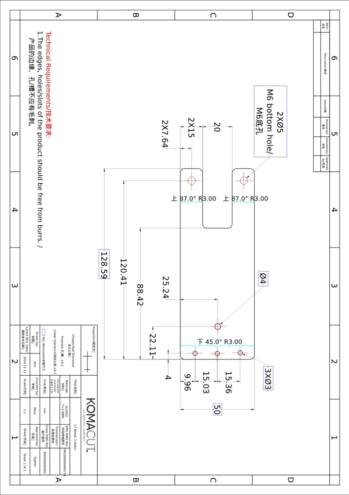
Fig. 3: PDF Drawing Example
2D Sheet Metal Drawings
2D drawings provide a flat representation of a sheet metal component and are particularly useful for simple designs.
While 3D drawings are primarily used for most projects, having both 2D and 3D drawings is always beneficial. For certain fabrication processes, 2D drawings are essential.
These are required for:
- Components that will be bent, laser cut, or CNC turned.
- Components featuring countersinks, counterbores, threaded holes, bend angles, blind holes, or laser engraving.
- Components with milled features, such as edge fillets or chamfers.
Key Components of a 2D Drawing:
2D drawings should be annotated with all the information required in fabrication.
Some basic information that should be included is:
- Company name, part number and drawing revision number
- Scale and measurement units
- Material information
The drawing should also show all the dimensions and features of the component and be annotated to show the fabrication processes that will be applied. A complete 2D sheet metal drawing will clearly show:
- The dimensions of all bends, cuts, holes, countersinks, counterbores, flanges and other formed features.
- Critical tolerances, including dimensional, angular and other tolerances.
- Material thickness and thickness tolerances
Designs should also provide detailed information about surface finishing. Basic information about the type of finish should be shown as well as detailed information, such as color codes for colored finishes.
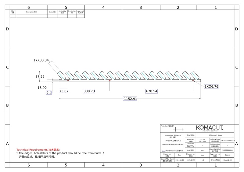
Fig. 4: 2D View (PDF), Unfolding
Isometric Views of the Part
It’s important to show multiple angles of a component. Normally, it’s best to provide three different angles.
Tolerances
Tolerances should be detailed on all sheet metal drawings.
It’s important not to set tolerances that are too strict. Advancements in manufacturing techniques have made it possible to achieve tight tolerances, but doing so can be more expensive. When you set tolerances, you should align them with the actual requirements and avoid using tight tolerances that do not add value to the function or structure of the component.
Tolerance markup methods:
- General tolerances for unspecified dimensions are normally displayed in the title block of the drawing. For example, the title block might read, “Unless otherwise specified, all dimensions are ± 0.1 mm.”
- Tolerances for specific dimensions are displayed with the dimension they apply to. For example, a specific dimension might be marked as 50.0 mm ± 0.2 mm.
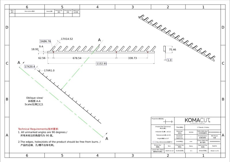
Fig. 5: 2D View (PDF), Oblique View
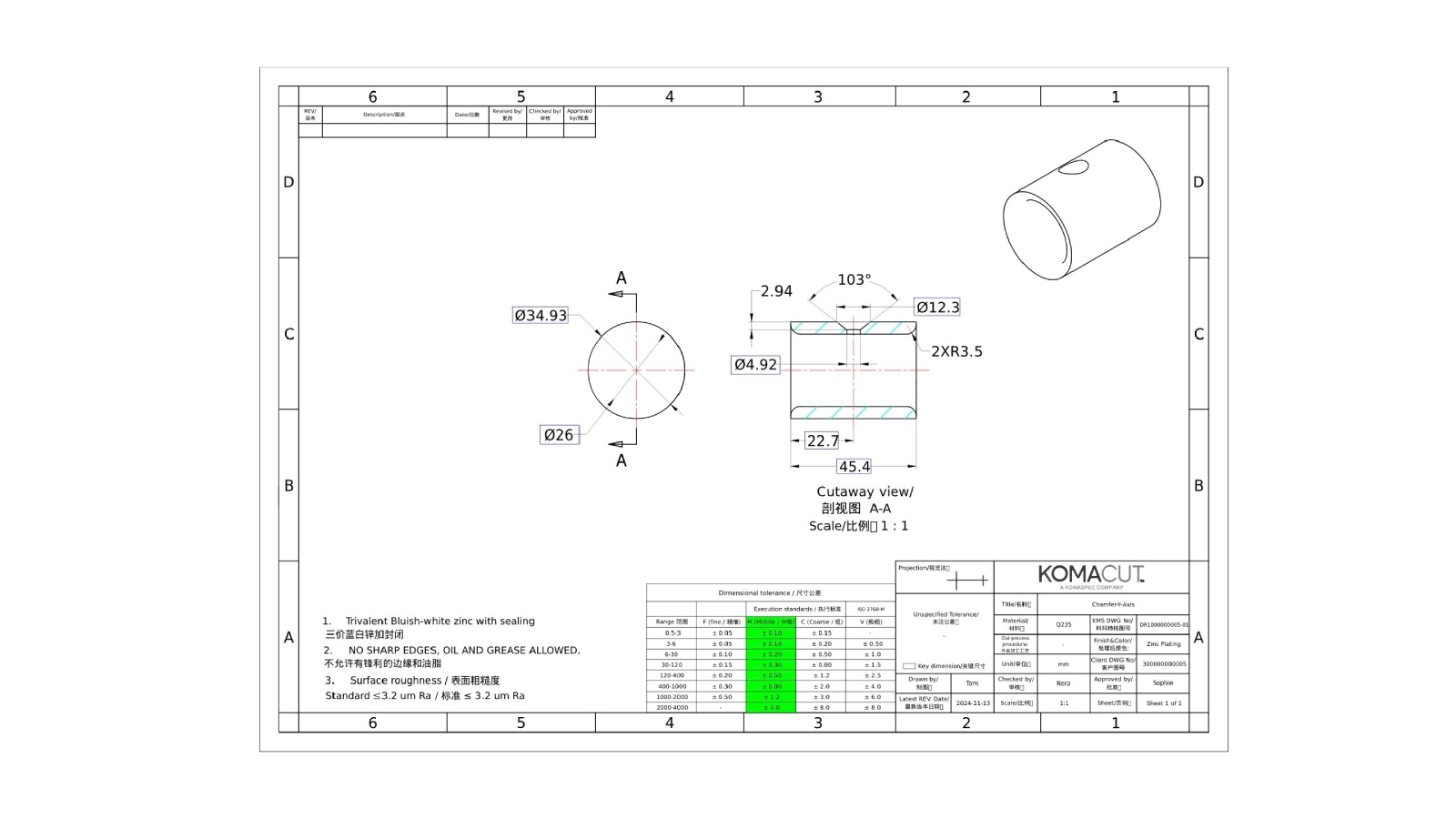
Features
All features should be clearly identified, supplied with clear and accurate dimensions and shown with any relevant specifications. Holes, for example, should be identified as either threaded or through holes, with specifications provided for threading in threaded holes.
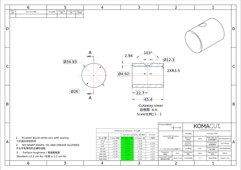
Fig. 6: 2D View (PDF), Chamfer
Flat Pattern Drawings and CNC Bent Parts
Flat pattern diagrams are used in CNC bending. A flat pattern drawing is a 2D overhead view of a sheet metal component. They are helpful in the planning stage, allowing a manufacturer to plan material use more quickly, speeding up quoting time and fabrication planning time.
As other special considerations, drawings for parts that will be bent should also feature:
- Angular tolerances
- Relevant isometric views – isometric views are important for parts that will be bent
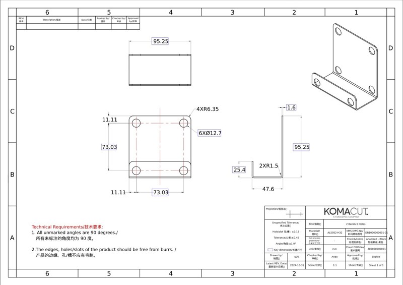
Fig. 7: 2D View (PDF) - CNC Bent Part
Supported File Formats
2D drawings should be supplied in a manufacturer-supported file type. DWG and DXF files are commonly used for 2D drawings, with DXF being the most widely recognized. Almost all CAD software can import and export DXF files using a CAM or DXF plugin, making it a universal format for manufacturers worldwide.
For parts with bends, ensure they are exported using the specified DXF layer map.
| Layer | Description |
|---|---|
| X Layer - 0F | Solid geometry Everything except defined in the following layers |
| X Layer 1F | Bend Down bend lines only No other entities |
| X Layer 2F | Bend up bend lines only No other entities |
| X Layer 3F | Bounding Box layer |
| X Layer 4F | Sketches |
Table 1: Layer Specifications
Different CAD software can have more or fewer options available for layer mapping. The option given above is available with most applications.
PDF copies of all designs should also be supplied for reference, record keeping and version control.
3D Sheet Metal Drawings
At Komacut, we mainly work with 3D drawings. With 3D drawings, we’re able to perform more calculations for accurate design for manufacturability feedback and optimal part pricing. Having 3D drawings allows for accurate nesting, part simulation and other processes.
For 3D drawings, the general rules apply:
- Single part drawings only, no assemblies or nested parts
- Parts should be solid models, created using sheet metal design modules
- Parts should be feasible for production from sheet metal
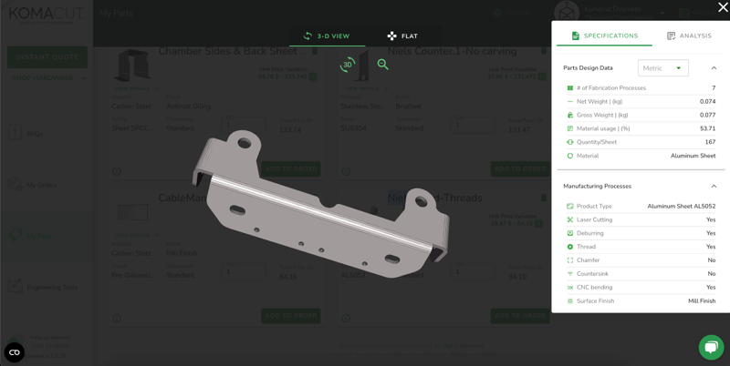
Fig. 8: 3D View - Sheet Metal Part
Tolerances and Features
While there is some 3D software which allows for noting tolerances and other details directly in the 3D, most 3D drawings are only showing the nominal (desired) dimension, and do not show the tolerance or what range of dimensions is acceptable. This is why 2D drawings are so vital in checking the part manufacturability and during quality control. In the absence of a 2D drawing, manufacturers will use standard tolerances.
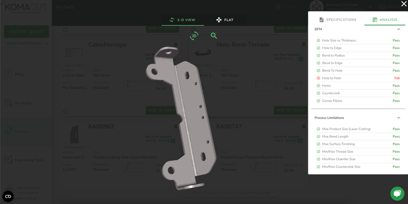
Fig. 9: 3D View - Part Analysis
Supported File Formats
3D sheet metal component drawings should be made with purpose built sheet metal design software and supplied in a manufacturer supported file format. Drawings should also be solid objects and not planes.
Some widely accepted 3D file formats are:
- STP (File Extension: .stp)
- STEP (File extension: .step)
- SolidWorks (File extension: .sldprt)
Note that it’s best to use STP or STEP files with 3D drawings because these are universally accepted file format that can be converted without losing detail or being corrupted.
| Drawing Type | Typical File Format | Essential For | Special Considerations |
|---|---|---|---|
| 2D | DXF | CNC bending | Isometric views required Flat pattern drawings required for bent components |
| 3D | STP, STEP and SolidWorks | Complicated designs | 3D drawings allow a manufacturer to better optimize designs for manufacturability |
Table 2: Drawing Types and Formats for Manufacturing
Summary
High quality designs will save you time, help you avoid mistakes, and they could save you money in manufacturing. You can follow the guidelines we’ve set out here to make sure you’re addressing the key factors in sheet metal component designs. Make sure you always supply all the necessary details in your designs and that your designs match your fabricator’s requirements.