
- Key Takeaways
- What Is a Chamfer?
- Chamfer vs. Bevel vs. Fillet vs. Break Edges
- What Are Chamfers Used For?
- Types of Chamfers
- How Are Chamfers Made?
- How to Dimension a Chamfer on a Drawing
- 3 Best Practices When Specifying Chamfers
- Specifying Chamfers on Sheet Metal Parts
- How Does Chamfering Affect the Cost of Sheet Metal Parts?
- FAQ
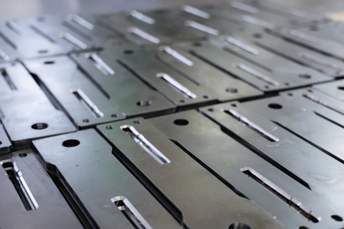
A chamfer refers to a flat cut made at the edge of a part where two of its faces meet.
Engineers add chamfers to parts in order to eliminate cutting hazards introduced by sharp edges, seat a countersunk screw flush, guide a pin or fastener into a hole, or create a surface area for a coating or weld.
Chamfers are typically cut at a 45° angle. On sheet metal, 30° and 60° chamfers are also quite common. And lead-in chamfers for seals can have angles that are as low as 15°.
That’s chamfers in a nutshell, but this guide will give you all the other details you need, including how they differ from bevels and fillets, the limits that apply when adding chamfers to parts made of laser-cut sheet metal, and the right way to specify a chamfer on your design.
Key Takeaways
A chamfer is a flat surface that is produced by cutting off a portion of a sharp edge.
Chamfering can be used to eliminate laceration hazards from sharp edges, provide a surface to apply coatings, act as a countersink for fasteners, and ease assembly.
The standard angle for chamfers is 45 degrees, although 30- and 60-degree chamfers are also common for sheet metal parts.
Fillets are similar to chamfers but leave a rounded surface at the edge where they are cut, rather than a flat one.
Table of Contents
- Key Takeaways
- What Is a Chamfer?
- Chamfer vs. Bevel vs. Fillet vs. Break Edges
- What Are Chamfers Used For?
- Types of Chamfers
- How Are Chamfers Made?
- How to Dimension a Chamfer on a Drawing
- 3 Best Practices When Specifying Chamfers
- Specifying Chamfers on Sheet Metal Parts
- How Does Chamfering Affect the Cost of Sheet Metal Parts?
- Frequently Asked Questions
What Is a Chamfer?
A chamfer’s geometry is defined by its distance and angle. Its distance refers to the cut’s depth, namely how far it extends from the position where the original edge was located. Its angle is measured from one of the faces from which it was cut.
For example, a 2 mm × 45° chamfer is one that removes a right-angled sliver that is 2 mm deep on both faces. But a 2 mm × 30° chamfer will be 2 mm deep on one face and about 3.5 mm on the other. That’s why you need to note exactly which of the faces the distance refers to, because on any chamfer that isn’t 45°, that number will differ for each face.
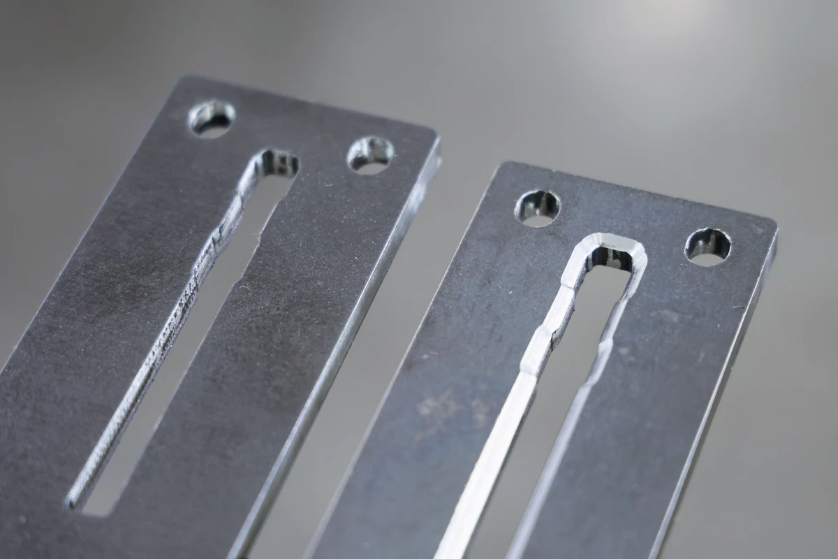
Under ISO conventions, the shorthand “C2” on a drawing represents a 2 mm × 45° chamfer. But under ASME Y14.5, the same chamfer needs to be spelled out as “2 × 45°.”
Chamfers can be cut into external edges, like corners or the end of a shaft, or into internal edges, like the entry of a bore or the mouth of a hole.
Chamfer vs. Bevel vs. Fillet vs. Break Edges
In carpentry, the terms “chamfer” and “bevel” are often used interchangeably. This causes confusion for machining, where the terms refer to distinct geometrical features, and mixing them up can be costly.
Edge Treatments Compared
| Edge treatment | Geometry | Typical callout | Uses |
|---|---|---|---|
| Chamfer | Flat, angled cut on part of the edge | 1 × 45°, C1 | Lead-in, countersink, deburr with a defined size, easy inspection |
| Bevel | Angled cut across the whole edge or face | Angle + remaining land | Weld preparation, large angled mating faces |
| Fillet / round | Curved transition with a defined radius | R1 | Stress reduction at loaded corners, coating coverage, cosmetic |
| Break edges | Small chamfer or radius, size not controlled | “Break all sharp edges 0.2–0.5” | Eliminating cutting hazards at sharp edges |
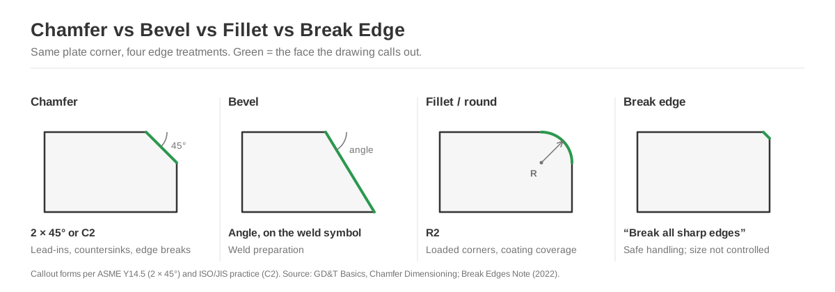
Chamfers and bevels are made using the same cutter. The difference between them is the extent of the cut. As defined by Harvey Performance Company, a chamfer is a shallow cut used to remove part of an edge, while a bevel is a more extensive cut used to angle the entire side of a feature. Because of this, the edge of a part can have two chamfers or one bevel but not both.
Like chamfers, fillets are cut into edges where two faces meet. But while chamfers leave a flat surface, fillets leave a rounded edge. This is not just a cosmetic feature, but also a way to reduce stress on those edges. According to a study in the Journal of Strain Analysis for Engineering Design, the abrupt change in diameter at unrounded edges causes higher stress concentration. Cutting a fillet into those corners lessens the stress it’s subjected to (giving it a finite stress concentration factor Kt). So if you’re designing a bracket that will be subject to cyclic load at an inside corner, specify a fillet radius instead of an angle (but specify a chamfer for its outside edges, since it machines faster and can be checked quickly with a gauge).
Most sheet metal designs should specify break edges instead of a chamfer. As GD&T Basics explains, “break edges” simply means the removal of sharp edges, without any precise angle or depth. With that note on the drawing, the shop can deburr using tumbling, belt, or hand tools.
What Are Chamfers Used For?
Lead-ins for assembly. A chamfer that’s been cut at the mouth of a hole or the end of a pin makes it easier for assemblers or users to fit mating parts together. A 45° chamfer is standard for metal-to-metal press fits, but the angle drops sharply for elastomer seals. For example, the O-ring manufacturer C. Otto Gehrckens uses a fitting chamfer of 15–20° to ensure that the ring deforms gradually, which prevents it from shearing on the edge. Always use the angle your seal supplier asks for instead of defaulting to the standard 45° cut.
Countersinks for flush fasteners. A countersink is a cone-shaped chamfer that runs along the edges of the hole. Its angle matches the underside of the screw head so the head sits flush with the surface.
According to Severance Tool, a hole intended for US flat-head screws (under ANSI B18.6.2) should have an 82° countersink, while metric screws (under ISO 10642 and DIN 7991) require one cut at a 90° angle, and aerospace fasteners use 100° countersinks.
Getting the angle right is essential for the assembly to fit properly. A screw with an 82° head fitted into a hole with a 90° countersink will sit proud, while a 90° head in an 82° hole will leave a gap instead of fitting flush. On drawings that include countersinks, make sure to call out the applicable fastener standard, not just the angle.
Thread starts. When designing tapped holes, placing a small chamfer at their entry gives the tap a centered start. It also removes the burr that forms at the first thread. Machine shops generally cut this with the same spot or countersink drill they used to start the hole.
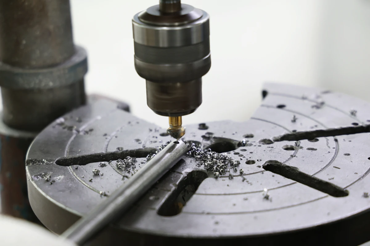
Deburring to remove laceration hazards. Parts with sheared or laser-cut edges can cut the skin when handled. This danger can be eliminated with a break-edge chamfer that’s only a few tenths of a millimeter deep. This is the most common use of chamfers and it does not require you to specify exact dimensions.
Better coverage for coatings. Sharp edges don’t take paint or powder coating very well. According to Coatings World, the coating tends to pull away from those edges as it cures, which could leave some areas bare and unprotected. As Rösler notes, the standard solution is rounding the edges before applying any coating to a sheet metal part. A chamfer is less ideal, since it still has two edges that could cause problems for the coating. But those two edges are obtuse rather than square, so a chamfer is still an improvement on a raw laser edge.
Preparing a part for welding. Adding a bevel to a thick plate can help the weld penetrate the full joint. This is another situation where the distinction matters – it’s specifically a bevel, not a chamfer, that should be called out for this task.
Types of Chamfers
To keep things clear, your drawing should denote each chamfer by its angle, location, and function.
For most applications, a 45-degree chamfer will be suitable. This is considered the default, results in a symmetrical surface, and it can be programmed quickly using a cutter that every shop already has on hand. If you’re designing a part made of sheet metal, you may also need 30- and 60-degree chamfers. And for seal lead-ins or countersinks, you will need to specify the angle that corresponds to the mating part.
Then there’s the location. An edge chamfer is one that runs along an edge (whether it’s straight or curved). A hole chamfer (countersink) is one that is placed along the mouth of a hole. A back chamfer is located on the far side of a through-hole but cut from the side the tool enters, which calls for a dedicated back-chamfering tool. And a corner chamfer is one that is cut at the vertex where three faces meet (in other words, a corner on the part’s profile).
Finally, chamfers can also be classified according to the function they’re meant to perform. A given chamfer could act as a break edge, lead-in, countersink, or simply a cosmetic feature. The chamfer’s function determines the tolerance it has to meet, so a lead-in on a press-fit bore needs a dimension and a tolerance, but a cosmetic edge located on the back of an enclosure can be cut with less precision.
How Are Chamfers Made?
It depends on the type of part.
For a machined part, the chamfer mill or countersink cuts it in one pass. According to Harvey Performance, deburring, spotting, countersinking, and chamfering can all be accomplished using the same tool (although with changes to the depth and feed). On turned parts, the lathe tool cuts the chamfer as part of the profile. This has very little effect on the cycle time. The costs only climb when you’re creating chamfers with non-standard angles because that requires the use of another tool.
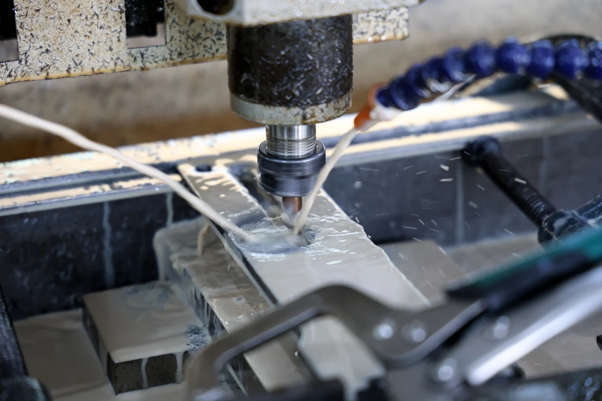
On sheet metal parts, chamfering is usually an additional operation. A standard flatbed laser will cut perpendicular to the sheet, which leaves a cut edge that is square apart from a slight kerf taper. To create the angled chamfer edge, you can either mill it, run the part through an edge-rounding machine (if you want to cut a radius instead of a defined angle), or use a laser that can handle bevels. Using a machine like the TRUMPF TruLaser 3000 Bevel Cut Edition gives you a cutting head you can tilt to produce chamfers with angles up to 50° in sheets that run as thick as 25 mm, though not every shop will have this kind of equipment on the floor. Design with milled or countersunk chamfers in mind, unless your supplier specifies otherwise.
How to Dimension a Chamfer on a Drawing
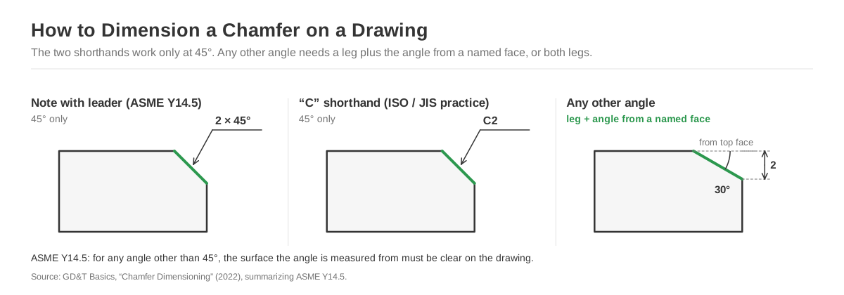
If you’re following ASME Y14.5, there are two methods for specifying the dimensions of a chamfer. One is to write the depth and angle. The other is to write the distances at both faces on the edges of the cut. As GD&T Basics points out, if you go with the former option and your angle is anything other than 45 degrees, it’s essential to clarify the surface against which the angle is measured. Noting “2 × 45°” with a leader to the edge is sufficient for a standard chamfer. But for a chamfer with any other angle, write the dimension on the face where it matters most and show the angle relative to that face. Alternatively, you can also write the dimensions for both legs and leave out the angle.
If you’re working to ISO or JIS drawing practice, you’ll often see the “C” shorthand (C1, C2, C0.5) instead. Under this system, the C designates a 45° chamfer and the number indicates the leg length. So for example, noting “C2” on a drawing refers to a standard chamfer with 2 mm depth. But if your drawing follows ASME conventions or your supplier is based in a location where the C shorthand is less common, write out the full formulation (depth + angle).
3 Best Practices When Specifying Chamfers
Include the chamfer in your part’s 3D model. CAM systems and platforms that provide instant quotes will read the model and miss any details that are only in your 2D drawing.
Only specify dimensions for chamfers that have an actual function. For edge breaks, you can simply write a general note like “break all sharp edges 0.2–0.5 mm unless otherwise specified.” This will simplify the drawing and cut down on inspection time.
Base the tolerance of each chamfer on its intended function. A lead-in that only needs to exist can carry ±0.3 mm, but a countersink that sets a screw head against a sealing gasket may need ±0.1 mm. Make sure to write the tolerance on the feature instead of relying on a title-block default.
Specifying Chamfers on Sheet Metal Parts
Limits are tighter for chamfers on sheet metal parts. That’s because the material is thinner than it is on machined parts, and it’s a separate operation from the cutting itself.
Komacut’s published limits are a good approximation of what most on-demand platforms will accept:
Komacut Chamfer Limits
| Parameter | Komacut limit |
|---|---|
| Accepted angles | 30°, 45°, 60°, each ±2° |
| Angle types per part | ≤ 2 |
| Maximum chamfer width | 6.0 mm |
| Positional (XYZ) tolerance | ±0.30 mm |
| Material thickness range | 1.6 mm to 20.0 mm |
| Maximum chamfer length | 300 mm |
| Maximum part size (unfolded) | 400 × 400 mm |
| Materials | Steel, stainless steel, aluminum |
Source: Komacut’s threading and chamfering capabilities and process tolerances.
As these limits reveal, there is a minimum thickness for chamfering. The reason is simple: if the sheet is too thin, the chamfer has nowhere to go. If you’re using 1.0 mm aluminum, a 45° chamfer consumes most of the edge. At that point, all you really need is a break edge. If the part needs a flush screw, add a countersunk hole in thicker stock, a dimpled (formed) countersink, or a self-clinching flush fastener instead of adding a machined countersink to the drawing.
Also worth noting that the only accepted angles are the standard trio of 30°, 45°, and 60°. So chamfers with angles that deviate from these will generally result in a manual quote. Usually, you can avoid this by going over the drawing and deciding whether each non-standard angle is genuinely needed. If you used an item from your CAD library that features a 40-degree chamfer, you can probably swap it out for a standard 45° chamfer without any real issue.
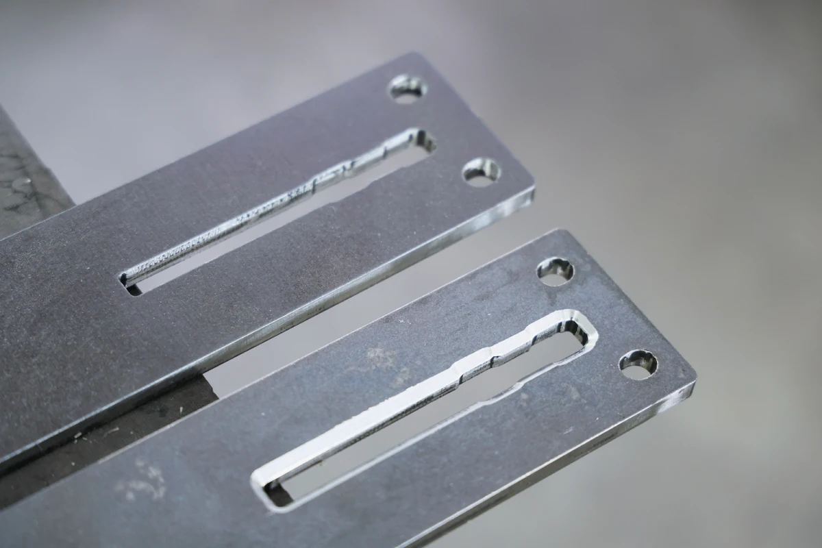
Finally, make sure to cross-check chamfer tolerances against the rest of the part. Our sheet metal tolerances guide will help you figure out those figures for bending and laser cutting. This step matters because a chamfer that has a tighter tolerance than the edge it’s been cut into can’t be inspected in any meaningful way.
How Does Chamfering Affect the Cost of Sheet Metal Parts?
The cost is mostly determined by the number of operations required to cut the chamfers. If there are multiple edges with the exact same 45° chamfer, those can all be done with the same setup. But if your design has two different types of chamfers, that means two setups, and the cost will reflect that. And if your part has three or more types of chamfer, then it falls outside Komacut’s published limit, and most platforms will push it to a manual quote.
Whenever possible, save the trouble and expense by using the same angle for every chamfer on your part.
Instant DFM Checking
Need pricing for your sheet metal part?
Upload your STEP file to Komacut and get an instant quote. Our automated DFM feedback flags manufacturability issues before you commit to an order.
Frequently Asked Questions
What is the purpose of a chamfer?
It depends on the application. In many cases, it simply removes a sharp edge and replaces it with a surface that is safer to handle. It can also be used to guide fasteners or pins into a hole for easier assembly, provide a countersink so screws can fit flush, or serve as a surface to hold welds or coatings.
Is a chamfer always 45 degrees?
No. 45 degrees is considered the default angle for chamfers because it is symmetrical and can be produced quickly. But on sheet metal, 30° and 60° are also standard. For countersinks, the chamfer will be angled to match the fastener (meaning 82° for ANSI flat heads or 90° for ISO metric). Lead-ins for seals will range from 15 to 20° to ensure the O-ring deforms gradually. When including a chamfer that isn’t 45 degrees on a drawing, specify which face the angle is measured from to ensure the resulting cut matches the intended design.
What is the difference between a chamfer and a bevel?
A chamfer is a shallow cut that removes part of an edge, while a bevel is a more significant cut that is used to angle an entire face or edge. Bevels are typically used when preparing thick plates for welding, while chamfers are the small edge features on sheet metal or machined parts.
What does chamfer C2 mean?
On a drawing, it is used as shorthand to designate a 45-degree chamfer cut at 2 mm of depth. This (along with the other C notations) is based on ISO and JIS drawing practice. Under ASME Y14.5, “2 × 45°” would be the equivalent notation. For any angles that are not represented by a C notation, specify the dimensions for both legs (or the dimension for one leg, the angle, and the face against which that angle is measured).
How do you measure a chamfer?
For small chamfers, use a chamfer gauge. It uses a cone or angled anvil to verify the chamfer dimensions. If the chamfer serves a critical purpose on the part, an optical comparator can ensure that it falls within the acceptable range. Another option is a depth micrometer combined with calipers to calculate the angle from the two legs. These tools make inspecting chamfers quick and easy, which is one reason they’re often preferred over rounded fillets.
Should I specify a chamfer or a countersink?
If it’s intended to house a flush screw head, go with a countersink. A countersink is essentially a conical chamfer with dimensions that correspond to standard fasteners. To make sure it can seat the screw properly, call out both the standard (ANSI or ISO) and the diameter of the screw head. For lead-ins or edge breaks, go with a plain chamfer. However, if your part is made of sheet metal that is thinner than 1.6 mm, neither option is suitable. In that case, specify a flush fastener or a formed countersink instead.