
- Key Takeaways
- What Is Kerf in Laser Cutting?
- How Wide Is a Typical Laser Kerf?
- What Affects Kerf Width?
- Should You Compensate for Kerf in Your CAD File?
- Kerf Isn't Tolerance
- Frequently Asked Questions
In laser cutting, kerf is the width of material the beam removes as it cuts.
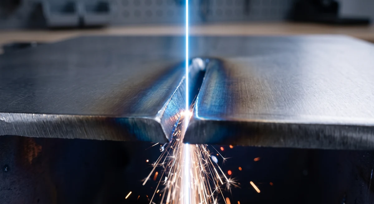
During the cutting process, a fiber laser melts and vaporizes a narrow channel through a sheet of metal, and the assist gas blows the molten metal clear. That channel is the kerf.
On sheet metal, the kerf typically runs 0.1-0.5 mm wide (depending on the material and its thickness). So if the machine you're using were to trace your CAD geometry exactly, every outside dimension would come out undersized by one kerf and every hole oversized by the same amount. Cutting machines account for this by offsetting the beam path by half the kerf.
For most parts, that's the whole story and the fabricator handles it. But when you're designing parts with interlocking features, press fits, and narrow slots, that's when kerf starts to matter.
Key Takeaways
Kerf is the width of the material that is removed by the cutting process.
For sheet metal, the kerf is typically somewhere between 0.1 mm and 0.5 mm.
The width of the kerf depends on the thickness of the material, the type of sheet metal used, and the settings of the cutting machine.
The kerf should not be included in the design of a part, since laser cutting machines already compensate for the kerf.
Table of Contents
What Is Kerf in Laser Cutting?
The term originally referred to the slot a sawblade leaves behind when cutting. A laser has no blade, but it leaves a similar gap.
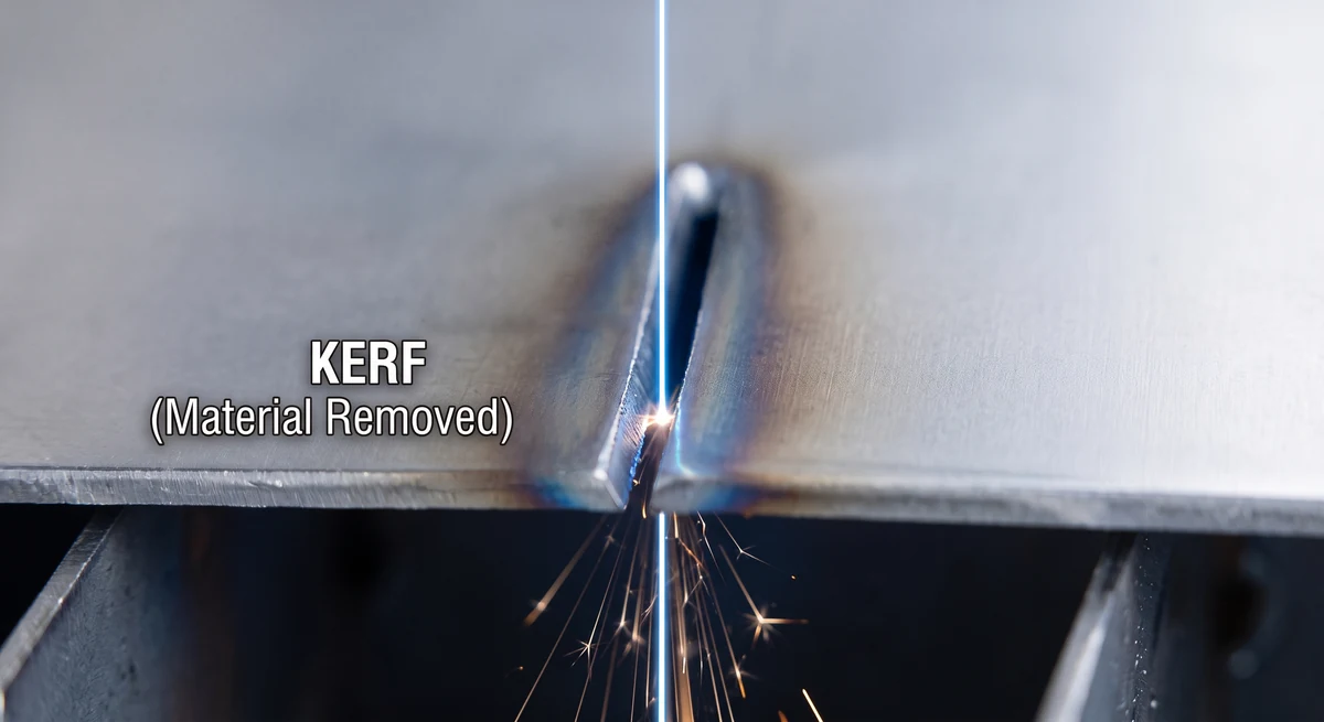
With a laser, the focused beam heats a small zone past its melting point, and pressurized assist gas (nitrogen, oxygen, or compressed air) ejects the molten material through the bottom of the sheet. The cut it leaves is always wider than the size of the beam, because heat conducts outward from the beam spot and melts the material beyond its edges.
Kerf is not a defect. It's an unavoidable part of any cutting process that removes material. Saws, waterjets, plasma, and lasers all leave a kerf.
The difference is that laser cutting leaves the narrowest kerf of all thermal cutting processes, which is one of the reasons it dominates precision sheet metal work. Less material removed means finer features, tighter nesting, and less heat pushed into the part.
How Wide Is a Typical Laser Kerf?
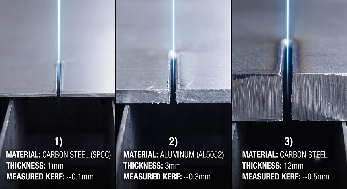
Reference data from laser equipment manufacturers puts fiber laser kerf between 0.1 mm and 0.5 mm for common sheet metal gauges. Generally speaking, the thicker the material, the wider the kerf:
Typical Kerf Width by Process and Material
| Process and material | Thickness | Typical kerf width |
|---|---|---|
| Fiber laser, carbon steel (SPCC/CRS) | 0.5–3 mm | 0.10–0.25 mm |
| Fiber laser, carbon steel | 4–12 mm | 0.25–0.50 mm |
| Fiber laser, aluminum (e.g. AL5052) | 1–3 mm | 0.15–0.35 mm |
| Fiber laser, thick plate | 15–25 mm | 0.6–1.0 mm |
| CO2 laser, sheet metal | 1–6 mm | 0.25–0.50 mm |
Two other details are worth mentioning here:
- Kerf Is Slightly Tapered: it is wider at the top surface where the beam enters, and narrower at the bottom where it exits (usually by 0.02 to 0.05 mm on a thin sheet).
- Kerf Isn't Perfectly Constant: Even on the same part, sharp corners and small holes concentrate heat and result in marginally wider cuts than on long straight runs.
Both of these effects are small on sheets under 3 mm, and both are why kerf values are quoted as ranges instead of single numbers.
What Affects Kerf Width?
The thickness of the material is the main factor. Thicker material needs more energy per millimeter of travel, causing the melt zone to grow and the kerf to widen.
Next is the type of material used. Carbon steel leaves the narrowest kerf. Aluminum runs wider at the same thickness because its thermal conductivity is several times that of steel, so heat spreads away from the beam spot and melts a broader channel. Stainless steel (SUS304) cut with nitrogen stays clean and narrow, close to carbon steel.
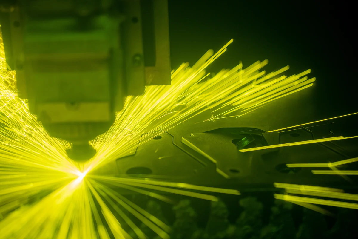
The rest is due to machine setup. Laser power, cutting speed, focus position, nozzle diameter, and assist gas pressure can all adjust the kerf width by hundredths of a millimeter.
Now, all this is the fabricator's problem, not yours. A manufacturer will dial in parameters based on material and thickness, measure the resulting kerf, and store the compensation value in their CAM software.
What you should take from this list is that kerf is a property of the material and the machine used to cut it, not the design. And this leads us to the question every engineer eventually asks.
Should You Compensate for Kerf in Your CAD File?
The simple answer is: no.
If you're ordering parts from a fabricator, model your part at nominal dimensions and let the manufacturer's CAM system apply kerf compensation. This is the standard workflow at every manufacturer, Komacut included.
The problem with doing it yourself is there's a risk of double compensation. If you offset your geometry by half a kerf, the machine's CAM software will then apply its own material-specific offset on top of yours. Then the measurements are off. Tabs come out oversized, slots come out undersized, and a batch of parts ends up being impossible to assemble. Because the error is barely visible, it doesn't get caught until someone tries (and fails) to fit Part A into Part B.
Note that this doesn't apply to fit clearance, which is different from kerf compensation. If you're designing tab-and-slot joints or press-fit features, the question isn't "how wide is the kerf?" but "how much clearance does this joint need?" That clearance should be an explicit feature of your design: for sheet metal tab-and-slot assembly, 0.05-0.1 mm per side gives a snug locating fit, and 0.2-0.3 mm per side gives an easy slip fit for weld fixturing. Put the clearance in the model as real geometry. That way, the parts will work no matter whose machine cuts them.
But if you're cutting on your own machine, that changes things. In this situation, you'll want to measure your kerf with a test cut (see the FAQ for more details) and set the offset in your nesting software once per material.
Kerf Isn't Tolerance
Engineers often conflate kerf and tolerance, but they're different numbers that represent different aspects of the design and cutting process. Kerf is how much material the beam removes. Tolerance is how far the finished dimension is allowed to deviate from nominal, after the manufacturer has already compensated for kerf.
What you should check before ordering is the tolerance spec, not the kerf. Komacut's published laser cutting tolerances are ±0.45 mm linear and ±0.12 mm on hole diameters as standard, or ±0.20 mm linear and ±0.08 mm on holes as high-precision, on material up to 20 mm thick. Those figures already account for kerf variation, taper, and thermal effects. If your design holds together at those numbers, kerf never needs to enter the conversation. If it doesn't (say, a bearing bore that needs ±0.02 mm), the solution isn't tighter laser settings, but a secondary machining operation on that feature.
Edge quality for thermal cuts is formally classified in ISO 9013, which is the standard to reference on a drawing if the perpendicularity or surface roughness of the cut edge matters for your application.
Instant DFM Checking
Try Komacut's instant quotation tool
Get fast, accurate cost estimates that factor in material and fabrication tolerances, so you can plan, budget, and refine your sheet metal parts with confidence.
Frequently Asked Questions
How do you measure laser kerf?
Cut a simple test shape (such as a 50 × 50 mm square) with compensation switched off, then measure it with calipers. The difference between the measured dimensions and the ones you programmed will be the width of one kerf (half a kerf per side). Alternatively, you can cut a single straight slit through a scrap of sheet metal and measure its width directly with feeler gauges.
Is kerf the same as cutting tolerance?
No. Kerf is the width of material the laser removes, while tolerance is how much the finished product is permitted to deviate from the nominal dimensions. Manufacturers compensate for kerf before cutting, so it's already accounted for in the quoted tolerance. Compare your design's requirements against the tolerance spec, not the kerf value.
Does kerf width vary by material?
Yes. Thicker material results in a wider melt zone, which leaves a larger kerf. Carbon steel cuts with the narrowest kerf (around 0.1-0.25 mm on a thin sheet). Aluminum cuts wider (roughly 0.15-0.35 mm) because its higher thermal conductivity spreads heat beyond the beam spot. Stainless steel cut with nitrogen stays close to carbon steel. Thickness matters even more than material: kerf width roughly doubles when you move from a 3 mm sheet to a 12 mm sheet.
Is fiber laser kerf narrower than CO2?
On thin sheet metal, yes. Fiber lasers focus to a smaller spot at the 1.06 µm wavelength, producing kerfs as narrow as 0.1 mm, while CO2 machines typically cut 0.25-0.5 mm kerfs. This is one reason fiber machines have largely replaced CO2 for cutting sheet metal, along with its faster cutting speeds and lower operating cost.
Do I need to account for kerf when ordering laser cut parts online?
No. Model your part at nominal dimensions. The machine will already compensate for kerf. Your parts are guaranteed to the published tolerance instead (at Komacut, ±0.45 mm standard or ±0.20 mm high-precision on linear dimensions). Only add explicit clearance where parts must fit together, such as tab-and-slot joints. See how ordering works at Komacut for more details.