
- Key Takeaways
- What is a CNC Machining Drawing?
- 2D CNC Machining Drawings
- 3D CNC Machining Drawings
- Summary
Having good drawings for CNC machining is crucial. At a minimum, drawings must be correct and contain all the information engineers and manufacturers need to fabricate a component. Beyond this, including more detailed and thorough information in designs can have additional benefits, such as saving time or even helping a manufacturer to work at a lower cost.
In this article, we’ll take a close look at designs for CNC machined parts and components. We’ll look at 2D, 3D and PDF designs, looking at what types of designs manufacturers need and what information each type of design should contain.
Key Takeaways
- 2D technical drawings are needed for CNC machining because they give important information to performance and costing such as surface roughness and tolerances that are difficult to encode in most 3D drawing formats.
- 3D drawings help for review and assembly checks, but they are not sufficient to produce or quote parts without tolerances and surface roughness.
- It’s best practice to provide 3Ds in a standard format such as STP or STEP.
What is a CNC Machining Drawing?
CNC machining drawings are design drawings used for manufacturing by CNC processes such as turning, milling or threading and chamfering.
- Part drawings come in 2D or 3D formats, and both types are usually needed to produce quality machined parts.
- 3D drawings (CADs) can be converted into manufacturing instructions (CAM files) and input into a CNC machine to be used directly for manufacture.
- 3D drawings also assist in visualizing the part, allowing engineers to analyze from a process or manufacturing point of view, as well as checking assembly relationships.
- 2D technical drawings are a “flash frame” which contain detailed tolerancing and notes regarding materials, finish, and other quality and manufacturing data.
2D Drawings
2D drawings are component design drawings that display vital information engineers use to correctly manufacture a component.
- They display basic information, such as the materials and finishing processes.
- They also show a component in an isometric view as well as how it will be fabricated through several highly detailed orthographic, section and detail views.
- Finally, any vital additional information needed in manufacturing is supplied as additional notes.
At Komacut, we require 2D drawings for all CNC machining projects.

3D Drawings
3D drawings are interactive drawings displayed through computer software that can be used to view a component from multiple angles. They show in detail how a component should look and function when completed, making it easier to visualize designs and understand manufacturing requirements.
They also include detailed technical information about how a component will be fabricated. While the information is not as complete as with 2D technical drawings, it can be uploaded directly to a CNC machine to create a G-code file used in fabrication.
PDF Files
PDF drawing files are used in CNC machining manufacturing for record keeping, version control and in approvals processes. PDFs can be created as a reference point and referred to when needed, as they are non-editable and secure. They’re often used during component quality control.
2D CNC Machining Drawings
2D technical drawings provide an isometric view for component visualization and tolerancing.
Key Components of a 2D Drawing
Here are the key pieces of information 2D drawings should contain.

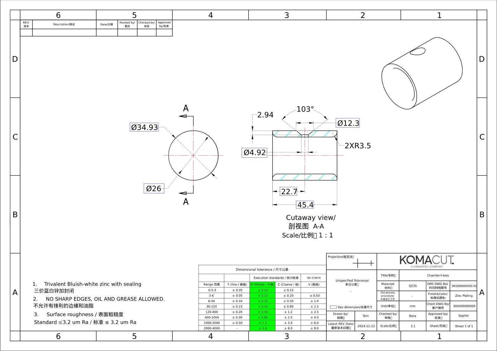
Material & Part Information (a)
2D drawings should have a title block that displays all necessary basic information about the part as well as information about the drawing itself. This includes:
- Company name, part number and drawing revision number
- Material and surface finish information
- Surface roughness requirements
- Drawing scale
- Standards used for tolerances
- The angle projection used in the drawing
Surface roughness is a measure of the texture of a surface created during a CNC machining process, quantified using measurements such as average roughness (Ra). Surface roughness should be specified in 2D design drawings.
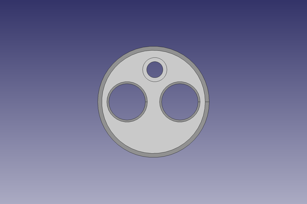
Isometric View of the Part (b)
It’s important to include at least one isometric view of the component to help engineers and manufacturers visualize it.
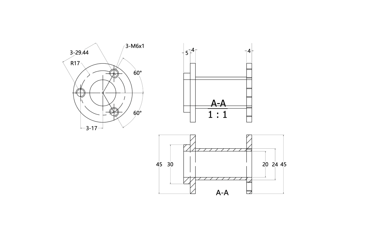
Orthographic, Section and Detail Views (c)
The bulk of the information in a 2D drawing is displayed in the orthographic, section and detail views. These are flat views that each show the component from one particular perspective.
- Orthographic views show the entire component from all sides necessary.
- Section views show a dissected view of the component and are used to display internal features.
- Detail views display detailed or complicated parts of an orthographic view.
- Critical tolerances
Features (c)
Features such as through-holes, holes, threading, countersinks, counterbores or chamfers should be marked with all information required for manufacture on a 2D drawing.
Tolerances (d)
Tolerances can be displayed for any dimension on a CNC drawing and should be detailed where necessary.
- Tolerances are an important design consideration, and tolerances need to be set to ensure a component will function correctly if only minimum accuracy is achieved.
- It’s also important, however, not to set tolerances that are too strict as they will add to cost with no benefit.
- Achievable tolerances also vary according to the materials and processes used. Tolerances differ between turning and milling, for example.
Tolerance markup methods:
- General tolerances for unspecified dimensions are normally displayed in the title block.
- The title block might read, “Unless otherwise specified, all dimensions are ± 0.1 mm.” If tolerance standards are followed, these can be displayed instead.
- Tolerances for specific dimensions are displayed with the dimension they apply to. For example, a specific dimension might be marked as 50.0 mm ± 0.2 mm.
- Critical dimensions can be boxed, or reference dimensions shown in parentheses
Additional Information (e)
2D drawings should also have a section showing any important additional information. This can be instructions to deburr sharp edges, for example.
Supported File Formats
2D drawings should be supplied in a manufacturer-supported type. At Komacut, we work with industry-standard DWG and DXF files.
- DXF files are the most widely used, and almost all CAD software can import and export DXF files using a CAM or DXF plugin.
- PDF files should also be supplied for specifications and details record keeping.
3D CNC Machining Drawings

At Komacut, we normally use 3D drawings alongside 2D drawings. 3D drawings are very useful for accurate design analysis and for calculations related to design for manufacturability. They also can be used to provide highly accurate nesting which can save material usage and contribute to reducing costs.
3D models are particularly useful for components and assemblies with complex geometry.
Komacut can update your old 3D drawings to the latest version and convert 2D drawings to 3D with our 3D CAD drafting and drawing revision service.
Key Components of a 3D Drawing
Here are the key components of a CNC design drawing.
Interactive 3D View
- 3D models provide is an interactive 3D view of a component that can be used to visualize it from every angle. This allows manufacturers to immediately see how a component will look and function when complete.
- They should be designed as a solid so that they can be manipulated, measured and checked
Tolerances, Features and Detailed Information

3D View of CNC Coupling – Key Specs
- Most 3D drawing software only allows you to show the nominal (desired) dimension and does not allow for showing tolerances, for example. Many other features and details, such as surface roughness requirements, aren’t displayed as well on 3D drawings.
- Some 3D software will allow you to display details on tolerances and other features directly in the drawing. If your software offers this feature, you should use it.
Design for Manufacturability Features
3D drawing software often comes with design for manufacturability features.
These are software features that alert designers and engineers to potential design improvements. Auto-calculations alert users to errors or opportunities to improve design. Designs can then be automatically iterated for optimized manufacturability. Without this software, design for manufacturability is a labor-intensive process.
Design for manufacturability software could identify opportunities to make tolerance requirements less strict, for example. Otherwise, it might ensure that features formed at one stage can be easily accessed at a later stage for another processes, such as welding. Otherwise, it might spot errors, such as holes located too close to bends or other features.

Instant DFM Analysis at b2b.komacut.com
Nesting Features
3D drawing software usually features nesting tools for optimizing the arrangement of sheet metal components on flat sections of sheet metal. This allows for minimizing waste in production and reducing production time, which ultimately reduces cost.
Nesting is not always as simple as it may seem. Requirements can depend on the process being used as well as factors like the number of parts being created and their size and shape.
Nesting software immediately identifies the optimal arrangement.
Machine Ready G-Code
3D drawings can be used to create a G-code that can be fed directly into a CAD machine. This allows for fast, basic programming for CAD manufacturing.
Supported File Formats
3D drawings should always be made with purpose-built sheet metal design software and supplied in a manufacturer-supported file format. Drawings should also be solid objects and not planes.
Some widely accepted 3D file formats are:
- STP (File Extension: .stp)
- STEP (File extension: .step)
- SolidWorks (File extension: .sldprt)
- Note that it’s best to use STP or STEP files with 3D drawings because they are universally accepted.
Note that it’s best to use STP or STEP files with 3D drawings because they are universally accepted.
Summary
- Having complete and accurate drawings is essential for CNC machining projects.
- Having both 2D and 3D drawing formats will also help to improve costing accuracy and speed and ensure part requirements are clearly communicated
- Make sure to review your drawings so you are sure your designs contain all the information they need.
2D and 3D File Reference Table
| Drawing Type | Typical File Format | Essential For | Special Considerations |
|---|---|---|---|
| 2D | DXF | All CNC machining processes | • Displays all information on formed features • Displays all critical tolerances |
| 3D | STP, STEP and SolidWorks | Particularly useful with complicated designs but helpful with all designs | Used as a basis for CAMs and helps with rapid part analysis for cost and manufacturability |